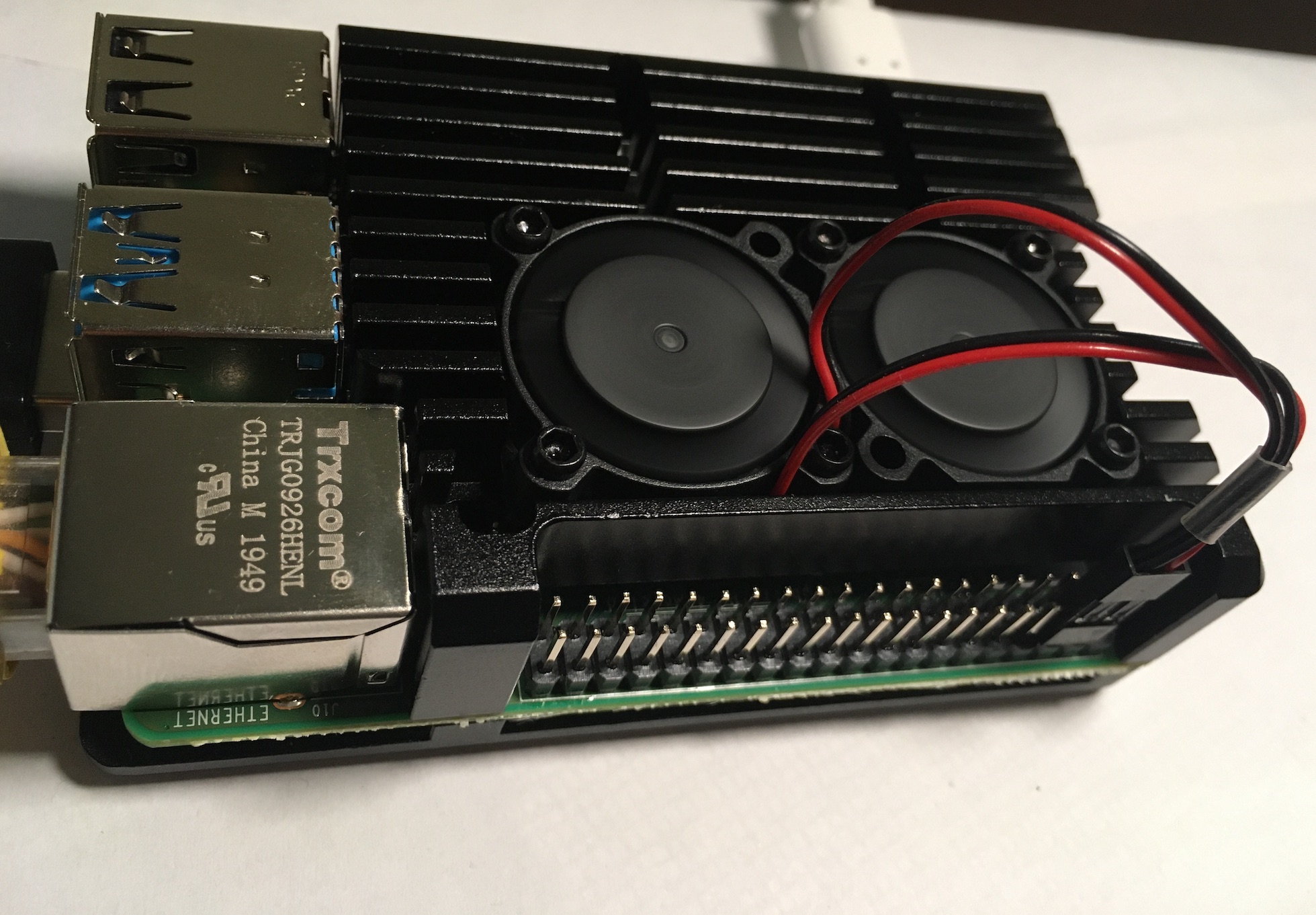
Several Raspberry Pi retailers are selling a CNC’d aluminium heatsink case for the Raspberry Pi, also known as the “Armour” case. While I actually wanted the passively cooled case (i.e. just a big heatsink), somehow I wound up with the dual-fan case instead.
The fans terminate in a combined dual-0.1″ plug, which they recommend connecting across the 5V and ground pins at positions 4 and 6 on the Pi’s GPIO header. This works fine, but the fans are on all the time, which I didn’t want (they’re not perfectly silent, and they’re also drawing power despite the Pi being relatively cool).
It would be better to switch the fans on when the Pi gets above a particular temperature – and this post explains how. Thanks to Jim for supplying hardware, knowledge and soldering skills to make a solution possible.
Software
From the software side, this is easily achieved. Some other sites recommend writing a userspace daemon in Python, but we can simply add a device-tree overlay to have the kernel do the monitoring and switching:
# in /boot/config.txt
dtoverlay=gpio-fan
By default, this sets GPIO12 high when the Pi hits 55C, and turns it off once the Pi gets below 45C. Theoretically, this also supports hardware PWM to control the fan speed, although the speed isn’t configurable through the overlay.
Hardware
So, how do we wire things up so that when GPIO12 goes high, we can supply the fans with the power they need? GPIO12 only supplies 3.3V and at most 16mA, so connecting the fans directly will damage the Pi. The hard-to-find gpio-fan overlay source code suggests using a 2N7002 N-MOSFET like so:
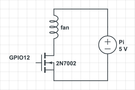
However, this doesn’t work for the dual-fans. And while it might work for single fans, there are still some additional improvements that can help protect the Pi.
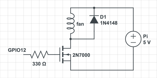
Flyback diode
The fan acts like an inductor, which means that there can be voltage spikes when we attempt to turn it off by cutting the voltage to the transistor but it keeps rotating due to inertia. We can eliminate this by introducing a flyback diode in parallel with the fans.

Gate resistor
The gate acts like a capacitor, which means there can be an “in-rush” current when it first charges. Placing a resistor between the GPIO and the gate keeps this current from reaching levels that would damage the Pi.
Pull-down resistor
When testing with sources other than the Pi’s GPIO, it’s useful to pull the MOSFET’s gate to ground. Without this, even after disconnecting the signal to the gate, the capacitance within the MOSFET will keep the fan connected to ground and the fan will continue to run.
This isn’t actually a big deal once the Pi has booted, because the Pi provides the equivalent when GPIO12 is driven low.

Fan current
None of the specifications I’ve found for the case hardware mention what the power consumption of the fans is. Connecting them up to a 5V power supply, I measured the current at about 200mA (for both fans running simultaneously in parallel). However, when I tried wiring them up with a 2N7000 N-channel MOSFET (with the gate driven at 3.3V) as suggested in the gpio-fan overlay source, they strained but couldn’t get started. The transistor was certainly “on”: I measured 5V across the fans, and 3.3V will saturate the 2N7000 according to the datasheet.
However, after reading into the graphs on the datasheet, I found the transistor will only allow about 100mA drain-source current at these voltages! The gate needs to be driven much higher (at say 5V) for the fans to get the 200mA they need… one 2N7000 transistor is not enough!

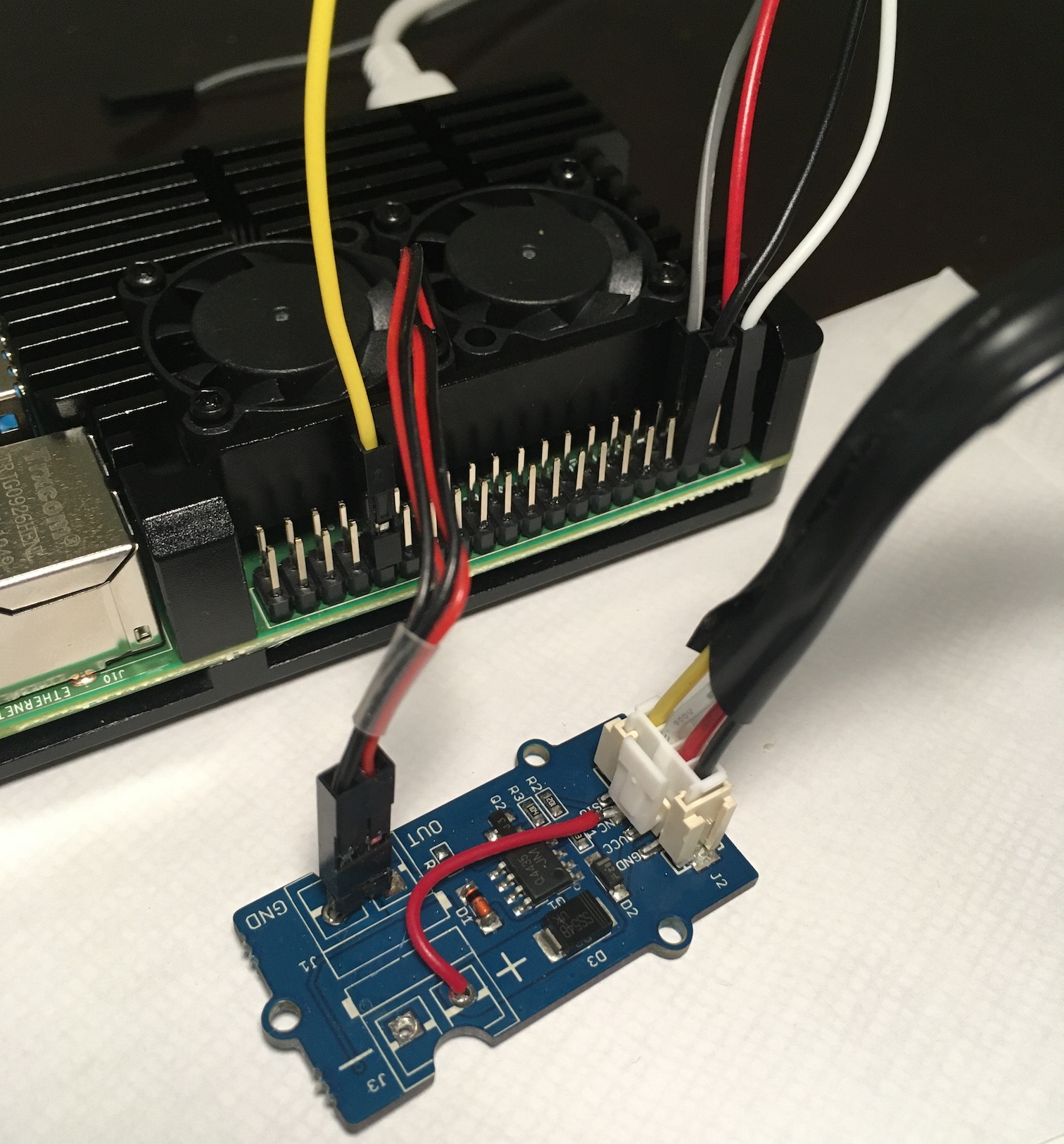
Grove board
While I could have built a more complex circuit by using a second transistor to use the 3.3V GPIO to switch 5V to the MOSFET gate, instead I ended up using a Grove MOSFET v1.1 module which already had all these improvements. Jim replaced the screw-in terminal blocks with 0.1″-pitch pins (for the existing fan plug) and re-used the spare lead in the Grover connector for the 5V source. This is a lot more compact than a breadboard with a bunch of large components on it, and works great!